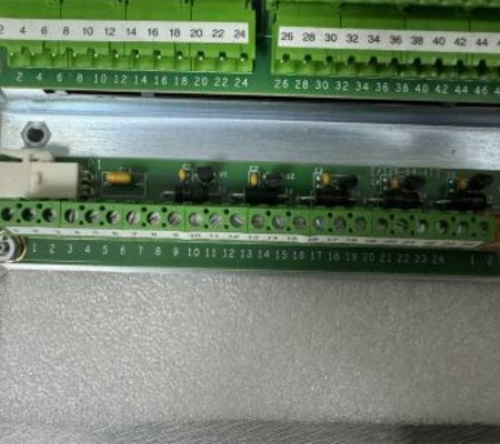
| Manufacture | GE |
| Item No | IS400JGPAG1ACD |
| Article number | IS400JGPAG1ACD |
| Series | Mark VIe |
| Origin | United States(US) |
| Dimension | 180*180*30(mm) |
| Weight | 0.8 kg |
| Customs Tariff Number | 85389091 |
| Type | ANALOG IN/OUT BOARD |
 The single-board controller is the heart of the system. The controller includes the main processor and redundant Ethernet drivers for communication with the networked I/O, as well as additional Ethernet drivers for the control network. The main processor and I/O modules use a real-time, multitasking operating system. The control software is in a configurable control block language stored in nonvolatile memory. The I/O network (IONet) is a proprietary, full-duplex, point-to-point protocol. It provides a deterministic, high-speed, 100 MB communications network for local or distributed I/O devices and provides communications between the main controller and networked I/O modules. The Mark VIe I/O module consists of three basic parts: the terminal block, the terminal box, and the I/O package. The barrier or box terminal box mounts to the terminal block, which mounts to a DIN rail or chassis in the control cabinet. The I/O package contains two Ethernet ports, a power supply, a local processor, and a data acquisition board.Frequently asked questions about the product are as follows: -What type of analog signals does the IS400JGPAG1ACD board handle? It handles standard 4-20 mA or 0-10 V analog signals common in industrial automation. It may also support other signal types, depending on the specific configuration and device. -What is the purpose of the IS400JGPAG1ACD board in a GE Mark VIe system? The IS400JGPAG1ACD board is used to interface the control system with analog field devices. It converts physical signals, such as temperature or pressure readings, into a digital format that the Mark VIe control system can process. -How is the IS400JGPAG1ACD board installed in a GE Mark VIe control system? The board is typically installed in one of the I/O racks or chassis in the system. It communicates with the central control unit over the system's communication bus. Installation involves physically mounting the board and connecting the field devices to the appropriate analog input/output terminals.