
| Manufacture | GE |
| Item No | IS200DAMAG1BCB |
| Article number | IS200DAMAG1BCB |
| Series | Mark VI |
| Origin | United States(US) |
| Dimension | 180*180*30(mm) |
| Weight | 0.8 kg |
| Customs Tariff Number | 85389091 |
| Type | Speedtronic Turbine Control PCB board |
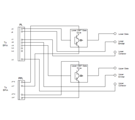 The DAMA, DAMB, and DAMC boards amplify current to provide the final stage of gate drive for the phase legs of the driver power bridge. They accept a +15/-7.5 supply input. The DAMD and DAME boards provide an unamplified interface with no supply input. The InnovationSeries™ 200DAM_ Gate Drive Amplifier and Interface Boards (DAM_) provide the interface between the control frame and the power switching devices (insulated gate bipolar transistors) of the InnovationSeries low voltage drivers. They include LEDs to indicate the on and off states of the IGBTs The gate drive boards are available in six variants, determined by the drive power rating DAMA 620 frame DAMB 375 frame DAMC 250 frame DAMD Glfor=180 frame: G2 for 125 or 92 G2 frameFrequently asked questions about the product are as follows: -What is the GE IS200DAMAG1BCB Speedtronic Turbine Control PCB Board? The IS200DAMAG1BCB is a printed circuit board (PCB) used in GE's Speedtronic turbine control systems. These systems are designed to control and protect gas and steam turbines. The IS200DAMAG1BCB board is involved in processing turbine signals, managing control parameters, and ensuring safe operation. -What components are on the IS200DAMAG1BCB PCB? The IS200DAMAG1BCB board contains various components, connectors for communication with other modules in the Speedtronic system. LEDs or indicators for indicating operating status and errors. -How do I replace the IS200DAMAG1BCB PCB? 1. Always shut down the turbine control system before removing or replacing components to prevent electrical damage or personal injury. 2. Carefully disconnect any wiring or communication cables connected to the board. Unscrew or loosen the board from its mounting. 3. Place the new IS200DAMAG1BCB circuit board into the mount and securely connect all cables and wires. 4. Turn the system back on and check for normal operation, ensuring there are no error codes or system alarms.